Hallo,
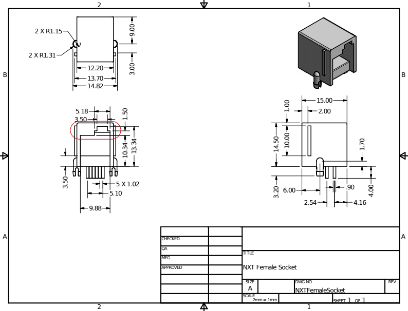
I am doing a pcb layout for this socket according to the drawing you supply on your website.
It occurred to me that this looks very much like a standard Wuerth Elektronik footprint.
Except the plastic lug positions are out by about 0.1 to 0.2 mm (4 mil to 8 mil) just enough to create annoyances when assembling.
So Question:
Is this originally a metric footprint perhaps supplied by Wuerth or similar?
I am working under the assumption that those sockets are still available from you in smallish quantities?
Hi Jan, thanks for the posting. We definitely still have these sockets available in sub-100 quantities. If you need more than 100, there will be some lead-time before we can acquire more.
We worked with Seeed studio to find an injection molding company that would be able to produce the custom socket needed for the NXT cables. They had a similar product (standard 6P6C modular connector socket) already in use, which they modified to support the offset latching tab, so perhaps they share a common footprint (as the footprint was unmodified for our needs). I wouldn’t be surprised if they chose to use this Weurth Elektronik footprint if it is a popular footprint for this type of socket.
If you want, I can make more precise measurements of the socket’s footprint to see exactly how far apart the plastic lugs are. Just let me know
I have checked around a bit: 12mm is a regular pitch between the plastic posts, but there are many others. 12.2 mm I have not seen (but that means nothing of course)
So could you measure the pitch between the plastic posts again please, if it is 12mm you should measure 472 mils.
The pitch between the closest row of pins and the plastic posts would then be 91 mils.
I am not sure how to include a file here, I would like to send you a footprint drawing.
Other than that: your beautiful pcb pattern with the 45 degree angled pads drives the kicad 3d viewer up the wall, and also old freecad (0.16).
I a not going to sort freecad. But I might file a bug report for kicad.
The first rain of the new summer season is falling. It is glorious outside.
Hi Jan, I granted you full user status so you should now be allowed to post links or upload an image. (New accounts start out as a somewhat-limited “new user” status for the first few weeks, sorry about that.)
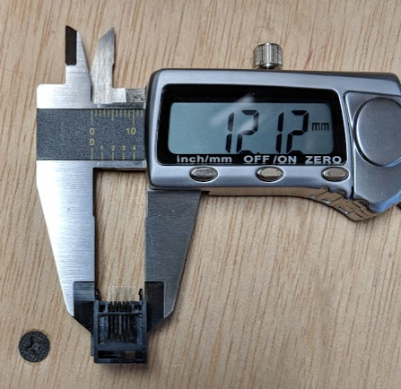
I took some further measurements this morning:
Distance between center of each peg: 12.12 mm. I noticed that the center of each peg is aligned with the edge of the socket body, so I measured the width of the socket body.
Distance between closest row of pins and the line connecting the two plastic posts: 2.04mm / 80 mil
I have stored the socket and calipers in my backpack so I can easily take further measurements if you need, just ask.
I haven’t used our pcb footprint in recent kicad versions so I will double-check to see what is happening with the 3d viewer!
In Minnesota we have reached the end of summertime heat and are entering into the wonderful cooler weather of autumn, it is truly my favorite time of the year here, with beautiful changing colors in the tree leaves, and a respite from the insects and humidity of summer
Regarding the 3d viewer, I just tried to view the breakout board in Kicad 5. It seems like sometimes it looks correct, but sometimes lots of things start to look weird, including the 1-6 pin labels on silkscreen and the normal header pin pads. I’ll keep trying to see what’s going on.
"Distance between closest row of pins and the line connecting the two plastic posts: 2.04mm / 80 mil
The breakout board measures 2.41 about in Kicad, maybe try again?
For the horizontal difference I have split the difference in half, for the vertical difference I might do the same. Then both sockets will fit just fine. Then I have a choice when there is no lego instrument, or when I want to make my own.
On the 3d viewer: When you use 90 degrees there is no problem it is the 45 degrees that messes.
I can drop you the 3d model as well, but it is not perfect for your socket. The back of the Wuerth socket is shorter.
I cant read drawings!
On the Wuerth drawing the housing indeed measures 12.2 mm.
But the locating pins are at 12 mm pitch. S’pose that’s to confuse the English or something.