Did a search but do not really see any info, is it possible to program the blinky grid via a usb cable?
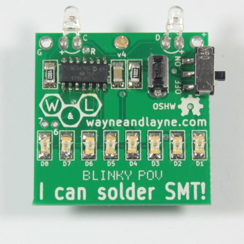
Hello, all of the Blinky kits support the standard Microchip PIC ICSP reprogramming method. On the Blinky Grid and Blinky POV, the five ICSP pins are on unpopulated header pins as shown in the photo below:

You can solder pins into those holes and connect your ICSP programmer, such as a pickit2 or pickit3 (or really any other PIC programmer). You can then use the pickit software to program a HEX file into the chip. We have all the firmware hex files posted here: https://www.wayneandlayne.com/projects/blinky/download/
For the Blinky Grid SMT, there wasn’t room to put the five pins together, but you can still reprogram the PIC chip. Either attach test leads to the five pins on the PIC itself:
- Chip pin 4 - MCLR / Vpp (reset/programming)
- Chip pin 1 - VDD (power supply)
- Chip pin 14 - VSS (ground)
- Chip pin 13 - ICSPDAT / UART TX / LED 6 (programming data)
- Chip pin 12 - ICSPCLK / UART RX / LED 7 (programming clock)
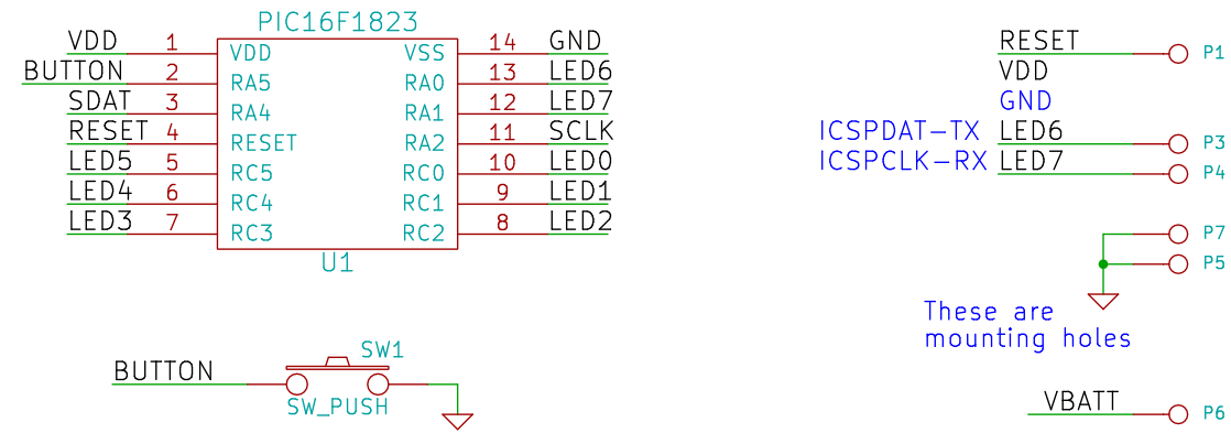
Or solder wires into these labeled holes:
- “R” - MCLR / Vpp (reset/programming)
- “+” - VDD (power supply)
- “G” - VSS (ground)
- “6” - ICSPDAT / UART TX / LED 6 (programming data)
- “7” - ICSPCLK / UART RX / LED 7 (programming clock)
Hope that helps, let me know if you have questions!
Thanks so much I will look at the info this weekend