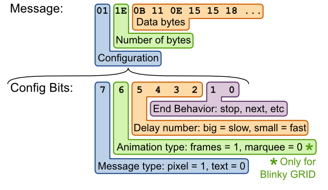
By using a camera in video mode and slowing down the clock speed of the programmer to 1000 msec, I was able to capture the bit stream of your default setting (it took about 132 MB of storage at that speed on my camera). I actually had to speak the bits into a voice recorder and then play it back and transcribe it to paper. The first seven bytes of info were 0E 00 00 06 01 1E 0B etc. The 0E represents 14 bytes in Intel Hex File format, which was accurate. The 0B represents 11 bytes in the message itself which was correct, and shown in Design Docs but not explained. The 01 was the configuration and the 1E was supposed to be the bytes in the message per your design docs. This corresponds to 30 bytes. The entire bit stream had 24 bytes of information (after the checksum of C3 there was 00 00 00 01 FF). How come the 1E doesn’t correspond to any length of bytes that I can see in the message? Also what does the 00 00 00 01 FF, after the checksum, represent? By the way the Blinky Grid kit worked fine. I never heard of Charlieplexing before so this was a learning experience for me.
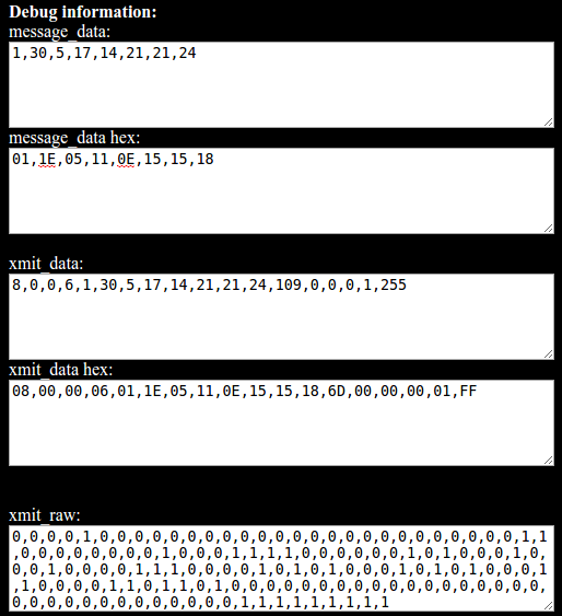
Hi Jim, thanks for the message. I always appreciate people double-checking and digging into the technical details of our projects! That’s a cool approach to slow down the data and transcribe it. You can also really increase the programming delay from the default of 40 ms to something very long like 1000-5000 ms, and write down the color of the data square each time the clock square changes. Also, we added a secret debug mode to the programmer website that I don’t think I’ve told anyone about before. If you add “?debug” to the end of the blinky programmer website address, it shows a few additional boxes with the raw message bytes at the end of the webpage (the boxes are only updated when you press the Go button).
http://www.wayneandlayne.com/blinky_programmer/?debug
For a simple text-marquee-advance-delay7 message of “Hello”, this becomes (all bytes in hex):
01,1E,05,11,0E,15,15,18
The first byte 01 is the overall number of messages (1 here). The second byte (1E) is the config byte of the first message, meaning text message, marquee message, delay7, advance after mesage. The third byte (05) is the number of bytes in the message (H-E-L-L-O). Then the five characters of the message itself.

From here we wrap the message bytes in the hex records:
08,00,00,06,01,1E,05,11,0E,15,15,18,6D,00,00,00,01,FF
The first byte (08) is the number of data bytes in this record, which are the 8 bytes above. The second and third bytes are the address (0000). The fourth byte (06) is the record type, which is a custom record type we just made up for the blinky transmission protocol (types 0-5 are already in use). Then we have the eight data bytes 01…18, plus the checksum (6D).
The “00,00,00,01,FF” bytes are the final record. Data bytes = 00, address = 0000, record type = 01, (no data bytes), and the checksum = FF. This record type is “End of File”, and signals the blinky bootloader code to start running the user code with the newly-uploaded messages.
So, now to the bytes you pasted:
0E - 14 bytes in this record
0000 - Store to address 0
06 - Record type 06 (New blinky messages)
01 - (first actual data byte = 1 message to come)
1E - (second data byte = Message 1 configuration byte)
0B - (third data byte = Message 1 number of bytes)
…
00 00 00 01 FF (record type 1 = start running the blinky code)
I hope that helps, but let me know if you have any further questions.
-Matthew
Matthew- thanks for your response. Your email makes sense. It seems that the documentation would be clearer on your website (and reproduced in your response to me) if the blue “L” shaped box (containing 01) to the right of the word “Message:” said “# of messages” (instead of “Configuration”); if the green “L” shaped box (containing 1E) said “Configuration” (instead of “Number of bytes”); the brown box is correct but it would be nice to point out that the “0B” is the number of bytes in the message. Also if the bracket describing the “Config Bits:” pointed to the green “L” shaped bracket (containing 1E) instead of the blue “L” shaped box. By the way I did use the Blinky_Programmer page to slow the response to 1000 msec. I tried writing down the bits (after recording them while watching when the colors changed) but became confused and made bit errors before too long unless I just dictated the response into a pocket recorder. I suppose if I slowed it down to 2000-5000 msec, I could have probably skipped the camera and just have used the recorder or paper directly.
Hi Jim. I think I see where the confusion is. The colorful diagram above describes just a single message, which is why the byte order is config, number of bytes, data bytes. Once we’ve prepared one or more messages, we prefix the message bytes with a top-level configuration byte, which is simply the message count:

I hope that makes sense. There are really two layers of configuration in this scheme: Each message has a config byte, “number of bytes” byte, and then the regular data bytes. Combine all those wrapped messages together, and add a top-level config byte (count of messages).
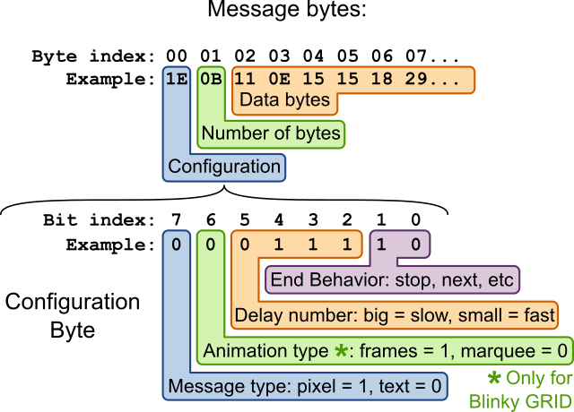
Matthew- your last email makes sense to me. Before you send any messages you put a prefix that is a byte containing the quantity of messages. In your Message Format section though, it seems to me that in the blue “L” box you should remove the 01 and put 1E because it makes sense as a Configuration byte (7 for the default Delay number); in the green “L” box you should remove the 1E and put 0B in it because that is the number of bytes in the default message; in the brown box you should remove the 0B and start with the 11 0E 15 15 18 . . . In the section about “Wrapping up the messages . . .” you should say that the Blinky_Programmer inserts a byte that is the message count before the first message or do you think that is understood from your diagram? I was wondering if the receiving microcontroller counted the messages or if it was the Programmer and I see now that it is the latter.
Ah, and now I’ve discovered my confusion. I hadn’t looked at the actual bytes in the message format image. You’re absolutely right, I should have those bytes match the default hello world message.
In the “Wrapping up the messages” section, I think I can differentiate between combining all the messages together with a prefix config byte (number of messages), and then describe how that entire string is divided into intel hex records for transmission.
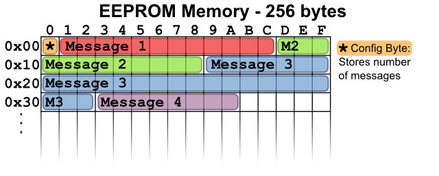
To your final comment, the bootloader and transmitter don’t ever try to understand the messages being loaded, they just send the raw bytes without inspection, and program them into the internal EEPROM memory. As far as the bootlaoder is concerned it is just storing some bytes into EEPROM, it has no way to parse or understand their meaning. The user code then reads and parses the message data from EEPROM, and uses the num_message byte to know how many messages are stored in the EEPROM.
I’ll make those updates to the webpage text itself later today, but the image re-work might need to wait for the weekend. Thanks for the suggestions and discussion, it’s been too-long since I last looked at the blinky programming details!
I just updated the messages image, let me know what you think.

Matthew,
I think the changes you made make sense. Thanks for you help.
Jim
Thanks much Jim, we truly appreciate the feedback.
