Missing one photodiode

I built a W&L Blinky Grid at DEFCON this year, and due to a tragic badge hacking accident one of the photodiodes has been destroyed (the epoxy melted, the junction is totally unrecoverable). I know I could simply buy another, but that doesn’t seem to be very in the spirit of DEFCON or of hardware hacking in general, so I’d like to know a few things:

  1. Is it safe to simply apply voltage (3.3v, I assume) in order to emulate the photodiode?
  2. Is there a way to dump the bits from the programming page?
  3. How fast is it safe to clock the “bus”?
  4. Should I give up on writing a programmer and just buy a $10 pack of photodiodes?

Many thanks.

Hello, thanks for the post. The light sensors are the TEPT4400 “ambient light sensors” (datasheet: http://www.vishay.com/docs/81341/tept4400.pdf).

TL;DR we can just send you more sensors if you like, fill out the contact form with your address and we’ll send them out.

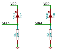
#1. Each sensor connects between the microcontroller analog input pin and +3.3v, and there is also a 10k resistor between that analog input pin and 0v. When the sensor is pointed at a black square on the screen, it has (effectively) a high internal resistance, so the 10k resistor pulls the analog input pin closer to ground. When the sensor is pointed at a white square on the screen, it has (effectively) a low internal resistance, so it pulls the analog input pin closer to VDD. Here’s the relevant part of the circuit schematic:

When you release the pushbutton during step 6 of programming (guide: http://www.wayneandlayne.com/files/blinky/images/programming_animated_gif/blinky_programming.gif) the bootloader code samples each sensor to determine the maximum voltage that corresponds to the “black” level. This is necessary due to variance of the parts involved. The measured value plus an offset (0x10, which is about 0.05 volts) is used as the threshold to determine whether the sensor is observing a “black” or “white” square.

You could directly apply a 3.3v voltage to the microcontroller input pins, as long as you kept the voltage low (near ground) up through step 6 of programming, so the auto-thresholding is “observing” a “black” voltage level. From there you could just use 0v and 3.3v to represent black and white respectively. Depending on the drive strength of whatever would be driving that signal, you might want to remove the 10k resistors and the remaining light sensor, to avoid messing up the transmitted signal.

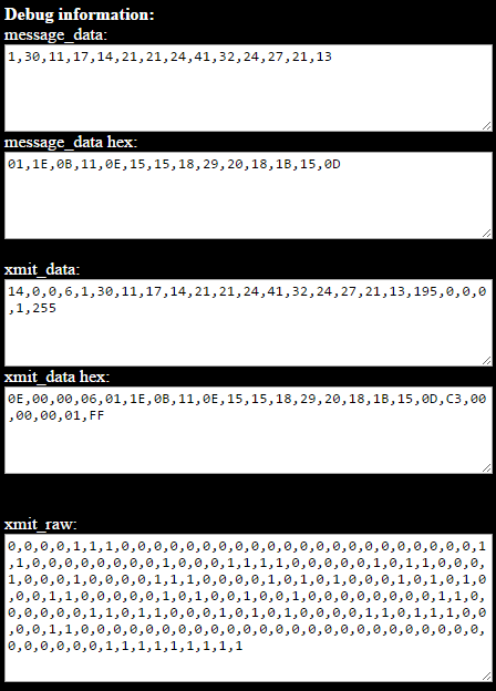
#2. Definitely! Add ?debug to the end of the programming page URL and it will show the details in textarea fields at the bottom of the page. The textareas are only updated when you press the Go button. http://www.wayneandlayne.com/blinky_programmer/?debug

message_data is the data we want to put into the EEPROM. First byte is the number of messages included. Then comes the bytes for each message in turn. Format of messages is described on the Design page.

xmit_data is the message data after it has been packaged into records like an Intel HEX file. Each record includes the number of data bytes, the destination address, the record type, the data bytes, and a checksum byte.

xmit_raw is the bitstream to transmit. Details are on the Design page but in brief, we use a clocked data transmission scheme where the data bit is sampled each time the clock bit transitions.

#3. With a clocked-data transmission scheme, the only critical timings are the relative edges of clock and data transitions. For the programmer webpage, there is a lot of software between when the javascript changes the div background-color and when the display actually changes the pixels, and we found a lot of variance due to hardware, drivers, display, and browser differences. If you’re directly bit-banging the bus you should be able to run it quite fast. There are some manual delays in the bootloader code when sampling the analog voltages of each pin, but you should be able to have the clock toggle every millisecond without issue. The EEPROM can only hold 256 bytes, so that should be pretty quick.

If there is any issue in programming, you’ll either see LEDs 3/4 flashing back and forth (checksum error, problem with data input) or you’ll see the display just stop changing (missed clock transitions, problem with clock input).

#4. I think it’d be super cool to have a wired blinky programmer, but time is valuable too :slight_smile: As I mentioned in the TL;DR at the top, we’re more than happy to mail you a couple of sensors for free, but I realize that probably doesn’t work with your travel, or the spirit of the challenge at hand. If you can find anyone with a PIC programmer (PIC16F1823) you could use that to edit the EEPROM bytes based on the debug output from the webpage.

Good luck, let us know how it goes!

I appreciate the offer of sending me a new sensor! Given the information you’ve posted, though, making a microcontroller based programmer should be pretty easy, and it would be a great way for me to get back in the firmware programming saddle.

Many thanks, and stay tuned for more info!

1 Like

OK, so I’m having an issue. I can get the LED to blink in time to the clock, and there’s definitely data on the data line, but when the programming is done, the grid is simply blank. Upon rebooting it, I get the same pattern that was programmed in before the sensor was destroyed. I’ve tried it with two messages.

The code is on Github Gist, but the forum won’t allow me to link it, so:

gist.github [DOT] com [SLASH] SilverWingedSeraph/aebf07d6f8ae6fec27235223ee149aa5

The circuit is merely pulldown (I also tried pull-up to 3.3v) resistors and wires going to the + side of each polarized footprint.

(I just bumped your account status from new user to regular member, so you should be able to post links now. We’re still getting the hang of administering Discourse…)

I think the issue might be that data is sampled on every transition of clock, both rising and falling edges of clock. It looks like your code is only setting new data before the rising edge of clock. Here’s some pseudocode for a loop:

set_data();
delay(x);

clock(high);
delay(x);

set_data();
delay(x);

clock(low);
delay(x);

repeat

OK, I’ve made the modifications. Now, rather than being stuck with all LEDs off, it is stuck with LED 2 on. Is there some type of finalization required beyond the given xmit_raw values?

https://gist.github.com/SilverWingedSeraph/aebf07d6f8ae6fec27235223ee149aa5

(Also, thanks!)

The LED should toggle state after each byte is received. As long as the inputs are near 0v during the button pressing part of the bootloader startup, it should be ok.

I would maybe add a delay(CL_DELAY); after each call to send_bit(), otherwise the data is changing and then shortly thereafter the clock is changing. It should be fine without but perhaps that would help.

Did you remove the sensor and/or the resistors? I think the resistors should be ok (but they will slow down how quickly the signals transition). Was there a reason you added the 47k resistors mentioned in the gist? They shouldn’t be needed with a push-pull driver pin like on the arduino (and most microcontrollers). The pull-down resistors were only part of the original schematic to act against the sensors’ pull-up operation.

You could increase your delay to maybe 1000, and then count clock transitions to see how often the LED state changes. IIRC the led should change state after every 8 transitions on the clock signal.

I did the suggested testing both with and without the additional pullup board, and with and without the onboard resistors. You’re correct that the additional resistors aren’t necessary, but the onboard ones definitely are - without them the BlinkyGrid didn’t detect the clock transitions at all. Adding a delay between setting the data bit and clocking the bus hasn’t had any effect.

Is the source code for the PIC on the BlinkyGrid available? I’d love to take a look at it and see what might be interacting badly.

That’s really strange that the onboard resistors are necessary. If your code was switching the output pins between “driving high” and “input”, then I would expect the pull-down resistors to be necessary to provide the low voltage when the pin was set to input, so that seems weird to me. If you have a voltage meter handy, try measuring the voltage at the PIC’s input pin 3 (data voltage input) and pin 11 (clock voltage input) during your programming process to see what voltage the blinky PIC is sampling.

The code is all open source: https://github.com/wayneandlayne/Blinky

Specifically, the bootloader code is here: https://github.com/wayneandlayne/blinky/blob/master/bootloader/bootloader.c

Here’s the source code for the programmer webpage, which contains some probably-terrible javascript to convert the messages into binary and also flash the squares: https://github.com/wayneandlayne/blinky/blob/master/blinkywww/index.php

I don’t think we had space in the chip’s flash to enable the debug print statements, sorry :frowning:

No worries on that! I just wanted to look at the logic.

I’m using an Arudino Due here, so the gates may not be push-pull. I don’t remember and I can’t find the datasheet right now.

I’m totally stumped on this one, I think I’ll come back to it tomorrow. So far, I know:

The programmer is putting out the right number of bits (14 bytes, 112 bits).
The clock works (due to testing in a prev. post).
The clock & data lines transition properly. (Checked with my scope.)
I have tried with and without final zeroing (clock and data to 0 at the end regardless of initial state).

Anyone who has any other ideas, please comment! The code is updated at the previously given gist link. Thanks @layne for all your help on this.

I’m 99% sure the Due is using push-pull for its outputs. If you checked the transitions with a scope then I’m sure that’s not the problem.

I’m curious enough that I’m going to try to reproduce this tonight after work. I’ll let you know how it goes.

Didn’t get around to this until today, sorry for the delay. I’ll let you know what I find.

Thanks for working on it! I’ve tried a few more things but I’m really at a dead end - I think I just don’t have the hardware expertise required.

Hey there, sorry for the delay, I just made time for this tonight.

I took an old blinky grid TH and removed the sensors and the two resistors. I soldered the two sensor pins on the PIC to wires, which I connected to an arduino mega 2560 I had on hand. I also connected the grid’s GND to arduino’s GND, and the grid’s power input to the 5v output from the arduino.

I took your code from your gist and the only modification I made was to change the pin numbers to 9 and 10, to match how I connected the wires. I ran the code and it worked perfectly! Nice work on the code. I was even able to change CL_DELAY from 50 down to 10 and it still programmed just fine.

So…if your code is perfect, it must be some sort of electrical issue or a bad connection to your blinky board’s sensor pins? I even tried moving my wires to be on 2 and 8 as you were doing, and it still worked perfectly…

Perhaps it’s something to do with the Leonardo? I think I have one hiding in my office that I can use. Let me try that…

I found the Leonardo and tested it out. Since the USB native serial port is always a bit tricky to get to connect and initialize before the 5 second delay finished, I added this code just after the Serial.begin(9600); line:

while (!Serial) {
    ; // wait for serial port to connect. Needed for native USB
  }

This way, on startup, it waits until you open the serial monitor before it continues. Once I did that, it worked just fine for reprogramming the blinky.

I made a really poor-quality video of the programming process on the mega: https://www.youtube.com/watch?v=qw9g-CFJoXA

So I’m not sure what to suggest, other than maybe try adding the while (!Serial); code from above.

Let me know how it goes!

Very weird. When I get access to my Arduinos again (I’m at away right now) I’ll definitely try it out. I really appreciate all your help on this! It’ll be nice to have a wired programmer.